I have been working on a community currency in the city in work and live in: De Haagse Munt. A complementary currency to stimulate collaboration, sharing and inclusion in our society. One of the ideas for implementation is to create a DIY payment terminal, so that for instance merchants can accept local currency. In theory, they could do so by using the Haagse Munt App, but it seems that a payment terminal can create more acceptance amongst the people who should use this system.
There are some requirements for such a device. So far, the list is as follows:
- Open source (hardware and software)
- Secure by design
- Use of phone and/or card
- Battery powered
- Resources friendly: As minimal computing power and standby power as possible
This will be a series of posts describing the process of creating this device. This is the list of articles published:
- RFID Reader with LED feedback and wooden enclosure
Part 1: RFID Reader with LED feedback and wooden enclosure
The first development iteration will focus om the basics: Create an RFID Reader with LED feedback and enclosure. Even though this is ‘basic’ stuff, there is still a lot of information to process and decisions to make. Let’s make a distinction between development chain, hardware, software, enclosure.
Development Chain
The development chain is the list of tools used to program the device. In my case I am using a Macbook Pro 2012 with the following tools:
- Atom editor. My preferred code editor.
- PlatformIO. This plugin for Atom (and other editors) is used to communicate with, and program the microcontroller.
- Homebrew. Package manager for macOS
I won’t go into details on how to install Atom and PlatformIO. There are enough tutorials for this, and it is not that complicated.
Hardware
Microcontroller
 Wemos Lolin D1 mini
Currently, the preferred piece of hardware for almost any IoT project is the ESP8266. I have multiple Wemos D1 mini’s laying around to develop with. This is a great little device for a very low price. It has WiFi on board and 4Mb flash memory. The esp can be programmed using the Arduino functions and libraries.
Wemos Lolin D1 mini
Currently, the preferred piece of hardware for almost any IoT project is the ESP8266. I have multiple Wemos D1 mini’s laying around to develop with. This is a great little device for a very low price. It has WiFi on board and 4Mb flash memory. The esp can be programmed using the Arduino functions and libraries.
RFID Scanner
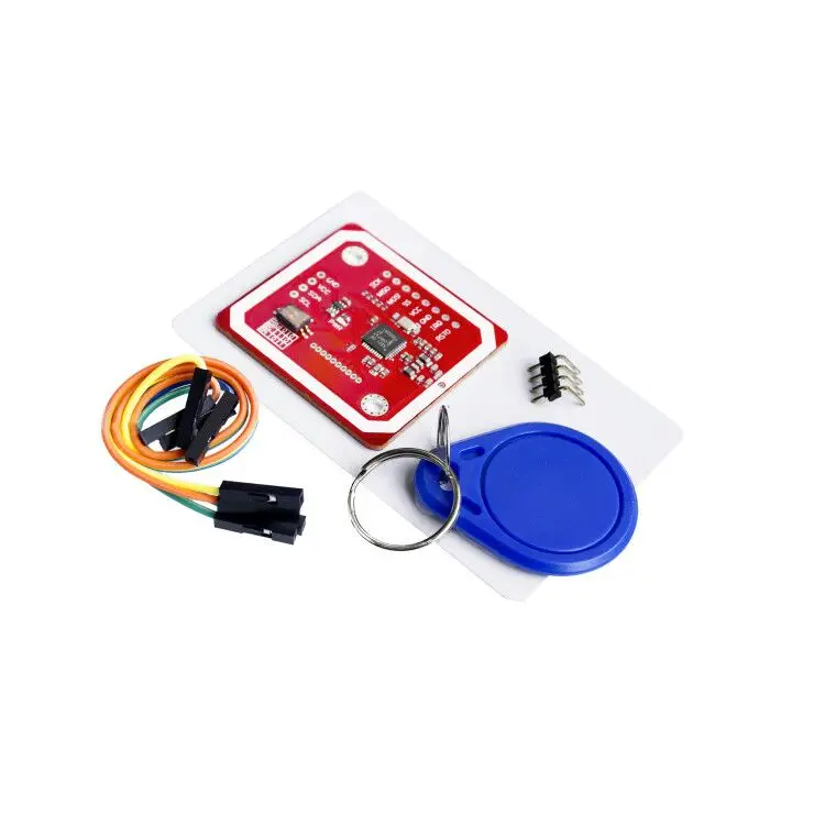 PN532 RFID reader
There are currently two RFID scanners on the market with a very low price level: the PN532 (€3,70) and the RC522 (€1,20). The RC522 is cheaper, but still my preferred RFID reader is the PN532, because of 3 reasons:
PN532 RFID reader
There are currently two RFID scanners on the market with a very low price level: the PN532 (€3,70) and the RC522 (€1,20). The RC522 is cheaper, but still my preferred RFID reader is the PN532, because of 3 reasons:
- This reader can read the Mifare Desfire EV1 cards (without modification), the preferred type of cards (to be used in a later iteration.
- The PN532 can read (most) Android NFC chips, so you can make contact using your phone!
- It seems there is a bit more library support for the PN532.
Lights (LED)

NeoPixel Ring
The connected lights provide visual feedback when the system performs an action, or when an error occurred. The neopixels are my favorite LED’s for these types of prototypes. The nice thing about these LED’s is that they can be programmed individually with only 1 wire (and pin) from the microcontroller! The NeoPixel Ring is selected for this project. This ring can provide a nice visual effect for the payment terminal.
Connections
Once you know how, it is not very difficult to connect all different hardware components. For the RFID scanner, we are using SWHSU (Software Serial HSU) mode, make sure the little dip-switches on the board are set to HSU mode (both switches to off). HSU uses only 4 wires, two for power, and two for communication (RX and TX). The labels on the bottom side of the board show which pin is which.
An overview of the connections:
RFID --> ESP8266
  GND --> GND
  VCC --> 5v
  TXD --> D2 (4, GPIO, I2C SCL)
  RXD --> D1 (5, GPIO, I2C SDA)
Neopixel --> ESP8266
  GND --> GND
  PWR --> 5v
  IN  --> D5 (14)
Software
The software is based on the Arduino platform and libraries. We use platform.io for building the firmware and to flash it to the microcontroller. We use 2 libraries for this: Adafruit Neopixel and Elechouse PN532. The first one can be installed using the platform.io ini file. The latter one we have to add to the lib folder in the project. Check the repository for details.
Clone the https://github.com/elechouse/PN532 repository in the libs folder of the project. git clone https://github.com/elechouse/PN532 Make sure the folder structure is like this: /lib/PN532/PN532.h and /lib/PN532_SWHSU/PN532_SWHSU.h
The platform.ini file now looks like this:
[env:d1]
 platform = espressif8266
 board = d1
 framework = arduino
 upload_port = /dev/cu.wchusbserial1420
 lib_deps =
   Adafruit NeoPixel@1.2.1
   ;https://github.com/elechouse/PN532
I initially tried to connect the PN532 using the I2C communication protocol. However, this did not work reliably. It has probably something to do with timing issues, but it is not really clear to me. I wanted to use I2C because you only use 4 wires for this (+, -, SCL, SCK). Then I found out you can actually use Software Serial HSU, which also uses 4 wires (+, -, TX, RX), the same pins for I2C can be used.
Enclosure
For the enclosure, I am using some standard 2×3 lumber. By sawing the top of you create a container for the electronics. [will be updated later]